Provide more Torque at Lower RPMs
How to choose the Right Gearhead: The appropriate use of gearing in your motion control application can make it run at lower rpms and provide more torque. Should you decide to use a gearhead, available configurations include an in-line or a right-angle gearhead. You must and also decide whether you want a motor with an integrated gearhead. The assembly includes both the gearhead and motor in a single housing.
Types of gearheads
In-line gearheads
In-line gearheads are commonly used for motion control applications because they have higher torque output and lower backlash than right-angle gearheads. They also cost less. In-line gearheads have an output shaft that is in line and centered with the motor shaft.
Right angle gearhead
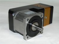 A right angle gearhead is commonly used when it’s necessary to fit a servo motor into a tight space. The output shaft of the right angle gearhead is at a 90-degree angle to the motor shaft. Therefore, most of the gearhead housing, and all of the motor housing, is parallel to the side of the machine, providing a smaller machine envelope. Note that some gearheads, such as worm gearheads, have an inherent right angle design because the drive axis of the worm (screw) is at a 90 degree angle to the axis of the worm gear.
Fig 1. A right-angle gearhead such as this is commonly used when it is necessary to fit a servo motor into a tight space
Separate motors and gearheads
Most motion control systems that employ gearing use separate motors and gearheads. This approach lets you choose the motor and gearhead most appropriate for the application, even when they come from different manufacturers. Typically, you can mount gearheads to just about any servo motor. All that is required is to mount the mating flanges together using standard screws. This configuration is more flexible than an integrated gearmotor and it’s easier to maintain. Gearheads wear out more quickly than the motor itself, so when a gearhead fails, you only have to replace it and not the motor.
Integrated gearmotors
That said, an integrated gearmotor is the best choice for certain applications. One advantage of this approach is the overall length of the assembly can be an inch or more shorter than an assembly with a separate gearhead and motor.
System design is simpler too because you only need a single speed and torque curve to determine if a gearmotor will provide the necessary performance to power your motion control system. This helps eliminate design errors.
And assembly is simpler as well. Because the gearhead and motor are integrated, it’s impossible make the assembly mistakes found when mounting a gearhead to a motor.
Use in food processing
Integrated gearmotors work well in harsh environments such as found in the food processing industry. Because gearmotor housings are also made with 300 grade stainless steel and must meet IP 69K standards for resistance to the ingress of high temperature-high pressure water, plant personnel can easily wash down machinery without having to worry about harming it. The design also eliminates the seam between the motor and the gearhead, so there is no place for food to get caught.
Flange-face gearheads
A newer trend is the use of flange-face gearheads. Instead of an output shaft, flange-face gearheads have a rotating disk with screw holes on the output. The machine being driven mounts directly to the flange. This arrangement eliminates the need for a flexible couple and all of its associated problems. Both gearheads and gearmotors are available with a flange face.
Fig 2. To mount a gearhead to a servo motor, all that is required is to attach the mating flanges together using standard screws. Here, a split collar mechanism on the input gear secures it to the motor shaft.
How to choose the right gearhead
There are many different types of gearheads for use in a motion control system. Knowing the attributes of each will help you make the best choice for different applications and determine how to choose the right gearhead:
- Spur gears have teeth that run perpendicular to the face of the gear. They are compact, cost-effective, and capable of high gear ratios. Disadvantages include they are noisy and prone to wear.
- Worm gear drives are used where it’s necessary to transmit power at a 90-degree angle and where high reductions are needed. Worm drives are precise, run quietly, and need little maintenance. Disadvantages include they are relatively low in efficiency and are non-reversible.
- Planetary gear drives are so called because the gear arrangement somewhat resembles the solar system. A central gear, called the sun gear, drives planetary gears positioned around it. The planetary gears rotate the output shaft of the gearhead. Advantages include compact size, high efficiency, low backlash, and a high torque to weight ratio. Disadvantages include complex design and high bearing loads.
- Harmonic gear drives contain a wave generator, flexispine, and circular spine. Advantages include low weight, compact design, no backlash, high gear ratios, high torque capability, and coaxial input and output. A disadvantage is the gears are prone to wear.
- Cycloidal drives have an input shaft that drives an eccectric bearing which then drives a cycloidal disk. Cycloidal speed reducers are capable of high ratios while remaining small in size. Disadvantages include increased vibration, caused by the cycloidal motion, which can cause wear on the cycloidal disk’s teeth.
Fig 3. You only need a single speed and torque curve to determine if an integrated gear motor such as this has the necessary performance to power the motion-control system.
For more information on how to choose the right gearhead and gearmotors for use in your design call Paul Hoerning at (920) 209 5303 or Travis Strebe at (920) 757 0500